
A lot of firmware lives or dies on a sensor it talks to over I2C. In CI, the usual move is to mock the driver. But mocking the driver tests your mock, not the I2C peripheral, the bus timing, or what the firmware does when the chip answers differently than expected. The BenchPod takes the other approach: it becomes the sensor on real wires, and then it watches the bus to tell you exactly what happened.
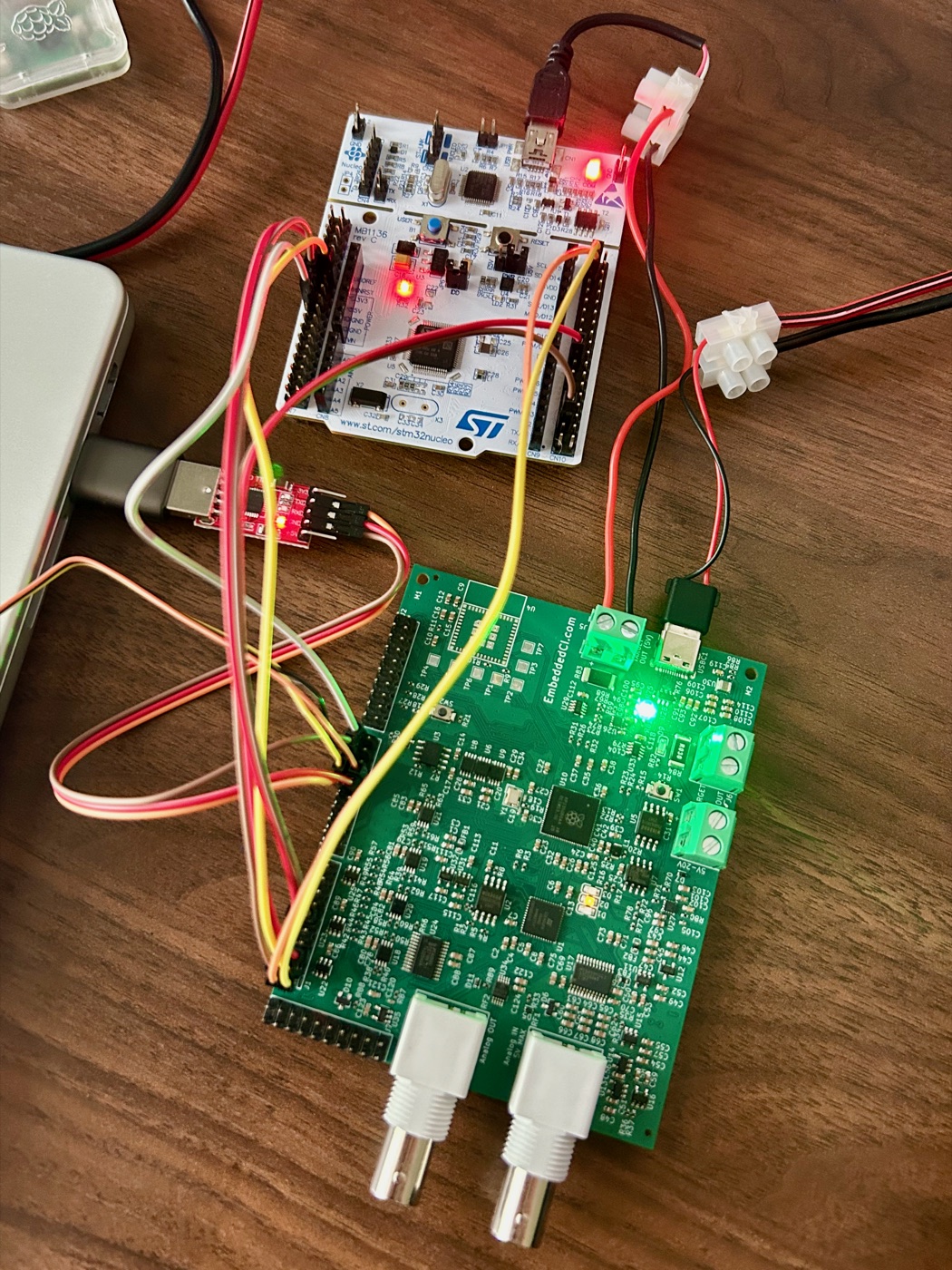
The pod as a BMP280
The pod can drive two of its logic-analyzer channels as an emulated I2C sensor (here a BMP280 from the public sensor library) while it captures the DUT's UART. The pod's channels are generic (PIN1 … PIN14); any signal can be on any of them. But I2C is open-drain and needs a pull-up, and only LA1-6 have pull-ups (LA1/2 = 4.7k, LA3/4 = 2.2k, LA5/6 = 10k; LA7/8 pull down), so the SDA/SCL lines must sit on one of those (here LA1/LA2). The pull-ups pull to the LA bank voltage; this example runs the bank at 3.3 V. You enable the pull-ups, then start the sensor with the values you want it to report:
from embeddedci.benchpod import BenchPod, INTERNAL, PIN1, PIN2, PIN5, PIN6, PIN11, PIN12

with BenchPod("192.168.1.213", la_voltage=3.3) as bp:   # board I/O voltage; 1.8 for a 1V8 board
    bp.flash(file="app.elf", target="target/stm32f4x.cfg",
             swclk=PIN11, swdio=PIN12, target_power=INTERNAL)

    # I2C is open-drain: enable the pod's pull-ups (LA1/2 = 4.7k), then become a BMP280.
    bp.enable_pullup(PIN1, PIN2)
    baro = bp.sensors.start("bmp280", pins={"sda": PIN1, "scl": PIN2},
                            values={"temperature_c": 22.5, "pressure_pa": 101000})

    # Power-cycle while capturing UART so the boot banner lands in the window.
    cap = bp.power_cycle_and_capture(rx=PIN5, tx=PIN6,
                                     delay=1.5, duration=6.0, until=r"APP_OK")
    assert cap.match("APP_OK")
    assert cap.match(r"chip id match=0x58|bmp280_detected=yes")
Now the firmware boots against a sensor that's really on the bus: no soldering, no breakout board, and the readings are whatever your test says they are. baro is a handle on that sensor: baro.set(...) changes a reading, baro.regs(0xD0, 1) reads its register image, baro.stop() takes it off the bus.
Assert on what the firmware did, not just that it booted
The interesting part: while the pod serves the sensor, it can also sample SDA and SCL. Decode that capture and you can check the actual transactions (the register pointer the driver wrote, the bytes it read back) instead of trusting a log line:
from embeddedci.benchpod import i2c

txns = baro.i2c_transactions(4096)
print(i2c.format_transactions(txns))
# -> S 0x76W+ 0xD0+ Sr 0x76R+ 0x58- P   (write reg 0xD0, read chip id 0x58)
assert i2c.read_register(txns, 0x76, 0xD0) == [0x58]
The decoder understands START / repeated-START / STOP, the R/W bit, per-byte ACK/NACK, and the common "write the register pointer, then read" pattern. So you're asserting that the driver probed 0xD0 and got the BMP280's 0x58 chip ID on the wire, which is what actually proves the integration works. baro.status() also counts the bytes the DUT wrote and shows the last one, for a quick "did it talk to me at all?".
Present, absent, and misbehaving
Because you control the sensor, you can test the paths that are hardest to reach on a desk:
- Present: the sensor answers; assert the firmware detects it and reads sane values.
- Absent: never start the sensor, or stop it mid-test; assert the firmware reports "not found" and fails safe instead of hanging on a probe.
- Misbehaving: inject a fault.
baro.fault("no_response", duration_s=2)stops acknowledging its address,baro.fault("stuck")freezes the reading,baro.fault("offset", param="temperature_c", value=5)reads 5 °C high, andbaro.fault("bus_stuck", duration_s=0.5)holds SDA low.baro.clear_fault()ends them.
That present/absent split is exactly the kind of branch that ships untested and then strands a device in the field the first time a sensor doesn't come up.
More than a BMP280
The library has more parts: the BME280 (temperature, pressure and humidity), Sensirion SHT4x and SHT3x, TI TMP117, the INA219 current monitor, the SCD4x CO2 sensor, the InvenSense MPU-6050, and SPI, UART and analog sensors too. Readings go in as values, and they can change while the DUT is reading. Several I2C sensors can share one bus:
hygro = bp.sensors.start("sht4x", pins={"sda": PIN1, "scl": PIN2},
                         values={"temperature_c": 21.0, "humidity_pct": 45.0})
hygro.set(humidity_pct=95.0)                    # does the firmware raise its condensation alarm?

imu = bp.sensors.start("mpu6050", pins={"sda": PIN1, "scl": PIN2}, values={"accel_z_g": 1.0})   # lying flat
imu.set(accel_x_g=0.0, accel_y_g=0.0, accel_z_g=-1.0)                                          # upside down
The emulated parts behave like the real ones where drivers notice: the MPU-6050 powers up asleep until the driver wakes it, scales its readings to the range the driver picks, and clears its soft reset on its own. bp.sensors.library() lists every entry, and imu.params gives each value's unit and range.
Your own sensor
Your part is not in the library? A sensor is a YAML file: its params, its I2C address, its registers, and the formulas from a reading to the bytes the driver sees. Start from the closest library entry and edit it:
open("tests/sensors/my_adc.yaml", "w").write(bp.sensors.library().text("tmp117"))
# ... edit the address, the registers and the formulas from your datasheet ...
bp.sensors.validate("tests/sensors/my_adc.yaml")          # compiles on the pod, keeps nothing
adc = bp.sensors.start("tests/sensors/my_adc.yaml", instance="adc", pins={"sda": PIN1, "scl": PIN2})
A compile error names the place, such as registers[4].s16be: unknown name 'ax' at 17. The format reference is on Emulated sensors, and a stimulus file plays values over time (a ramp, a step, a recorded CSV) with faults at chosen moments.
The pod can also play a GPS module: the library's gps_nmea prints NMEA sentences (RMC, GGA, GSV and the rest, like a u-blox receiver at 9600 baud) on one channel wired to the DUT's UART RX, from a second UART, so the DUT's console keeps working. Set a position, a speed and a course, and the fix moves; set fix=0 and the receiver loses its lock:
gps = bp.sensors.start("gps_nmea", pins={"tx": 9}, values={"lat_deg": 50.8466, "lon_deg": 4.3528, "sats": 9})
gps.set(speed_kmh=36, course_deg=90)                 # driving east
gps.set(fix=0)                                       # tunnel: no fix
More on that in Testing GPS Firmware Without the Sky.
Works over the LAN, USB and the cloud
The emulated sensors need firmware 3.10.3 or later and SDK 2.13.10 or later. The same test runs against a pod on your LAN, one on your desk over its USB-C cable (the USB network adapter, firmware 3.9.0 and later), or one in another building through embeddedci:<device-name>, with no code change. The Sensors tab in the web app plays the same definitions by hand, and the MCP server has them as tools (sensor_start, sensor_set, sensor_capture, ...). The full walkthrough and wiring table are in the pytest framework docs; for the analog side of the same bench, see Recording and Replaying Analog Signals.